
Configuration
The ASPEX configuration incorporates two distinct subsystems, namely the Solar Winds Ion Spectrometer (SWIS) and the Suprathermal and Energetic Particle Spectrometer (STEPS).
SWIS: Solar wind Ion Spectrometer
100 eV- 20 keV
Two planes: 2π in and across ecliptic
Species (H+ and He++) separated in the ecliptic and integrated across ecliptic
STEPS: Supra Thermal and Energetic Particle Spectrometer
20 keV/n – 5 MeV/n
Six directions
H+ and He++ separated -- Radial, Parker, Anti-sun,
H+ and He++ integrated -- Intermediate, North and South
SWIS configuration:
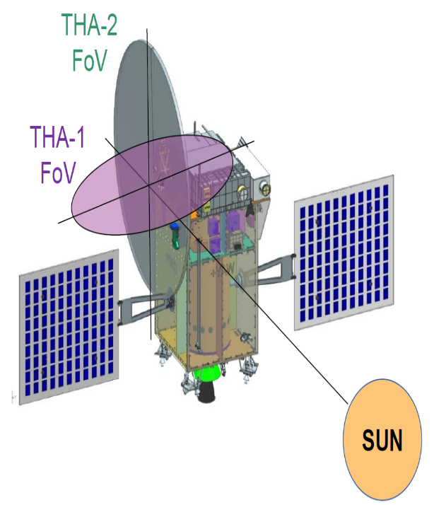
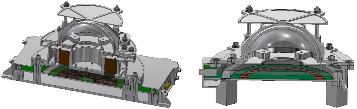
The SWIS system consists of two top-hat analyzers, each providing a 360-degree field of view in two mutually perpendicular planes, as depicted in Figure 2. To prevent obstruction in the Field of View (FOV), the two top-hat analyzers (THAs) are mounted on a tower assembly. Each of these THAs incorporates microchannel plate detectors (MCPs). Figure 3 illustrates the cutaway of both THAs, while Figure 4 displays the block schematic of the SWIS detector and its electronics. The SWIS subsystem comprises three distinct packages: THA-1, THA-2, and High Voltage Power Supplies, as mentioned below
- THA-1:
- Mounted on the top of the tower, providing a nearly 360o field of view in the ecliptic plane.
- Electrostatic analyzer (ESA) followed by a magnetic mass analyzer (MMA).
- MCP with a 16-sector radial position-sensitive anode.
- Front-end electronics
- Cutaway of THA-1 is shown in the left side of the Figure 3
- THA-2:
- Mounted on the side of the tower, providing a nearly 360o field of view perpendicular to the ecliptic plane.
- Electrostatic analyzer (ESA)
- MCP detector with a 32-sector anode
- Front-end electronics
- Cutaway of THA-2 is shown in the right side of the Figure 3.
- High Voltage Power Supplies:
- Provided for all elements of THA-1 and THA-2
STEPS configuration:
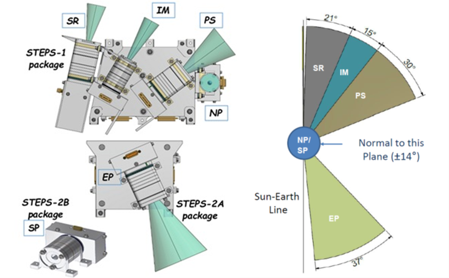
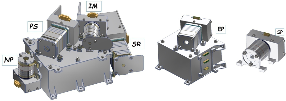
The STEPS instrument configuration consists of three distinct packages: STEPS-1, STEPS-2A, and STEPS-2B. The instrument employs custom-designed Si-PIN detectors to measure the spectrum of protons and alpha particles within the energy range of 20 keV/n to 5 MeV/n. This subsystem comprises a total of six detector units, with three units utilizing plastic scintillators in flag mode to separate protons and alpha particles. The other three units do not use plastic scintillators and operate in a species integrated mode. The plastic scintillator configuration enables the detection of ions with energies reaching up to 20 MeV. Each of the six detector units incorporates a magnetic assembly (MA) featuring SmCo permanent magnets to prevent electrons from reaching the detector and causing saturation.
The STEPS-1 package is positioned on the top deck of the spacecraft. Its primary function is to detect particles originating from the Sun in both the radial and along the Parker spiral directions within the Sun-Earth ecliptic plane. Additionally, it captures particles along the North direction, perpendicular to the Sun-Earth ecliptic plane. This is achieved through the utilization of four directional detector units.
The STEPS-2 package is further divided into two sub-packages, STEPS-2A and STEPS-2B, to ensure a clear Field of View (FOV). STEPS-2A is designed to detect particles coming from the Earth direction, while STEPS-2B focuses on particles arriving from the South direction across the Sun-Earth ecliptic plane.
Figure 4 provides a visual representation of the FOVs for different STEPS units, encompassing Sun-radial, intermediate, Parker Spiral, Earth-pointing (all in the ecliptic plane), and North and South pointing (perpendicular to the ecliptic plane). The CAD models of the STEPS units are presented in Figure 6, offering a detailed view of their physical configurations. The block schematic of STEPS, illustrated in Figure 7, delineates the instrument's interface with various subsystems on the spacecraft.
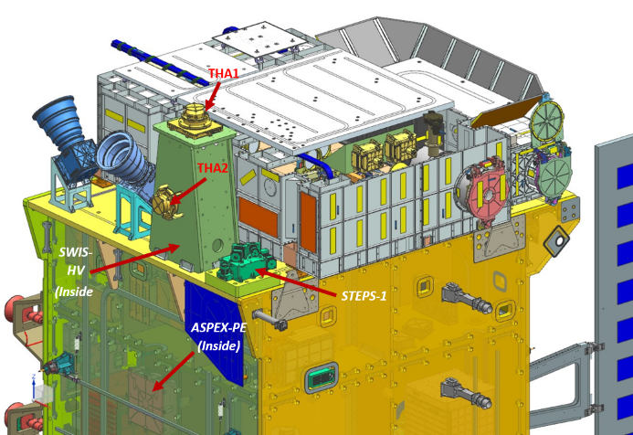
Common Processing Electronics:
The processing electronics package caters to the digitization of analog signal, processing the digitize data and handling various data interface with the spacecraft Onboard Computer (OBC). The ASPEX-PE package is situated below the top panel of the Aditya-L1 spacecraft. Figure 6 Shows the mounting location of all ASPEX subsystem on the Aditya-L1 satellite.